First test assembly went well. Soldering the SMDs wasn’t too bad once I’d worked out a strategy. They were added first, while the PCB could be held flat. You can just make out the SMD resistors in the picture – they are only 2mm long and 1.5mm wide! After that the top LEDs were added. These are 2.4mm “lighthouse” types that poke through the holes in the upper half of the UFO perfectly. The first UFO I did had green lights so I chose yellow for this one.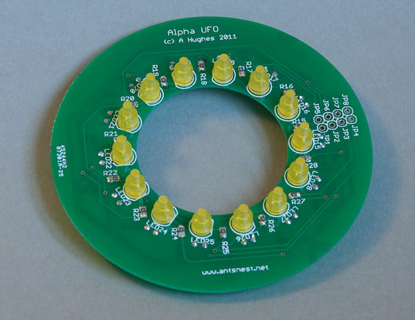
The bottom LEDS were added next – these are more tricky because they are bent almost flat with the PCB but such that they still point out of the windows in the bottom half of the UFO.
The PCB itself sits neatly inside the UFO. There are 8 connections to the controller board (seen at the right of the picture below) that must be brought out to the external controller which provides the animation. In the previous incarnation, these were fed through a small hole cut in the bottom and down a tube that was also used to hold the UFO aloft.
A quick electrical test revealed everything was working as expected! Amazing! I wasn’t expecting to get the layout perfect the first time. A satisfying day in all.
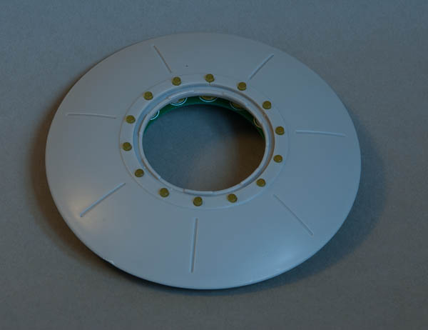
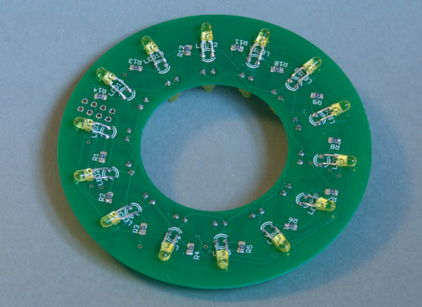
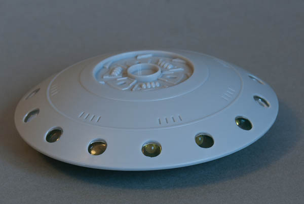
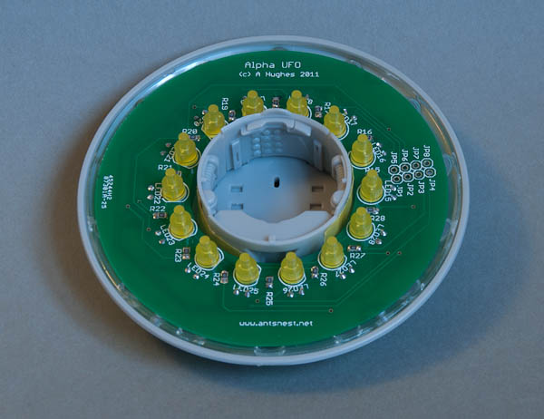
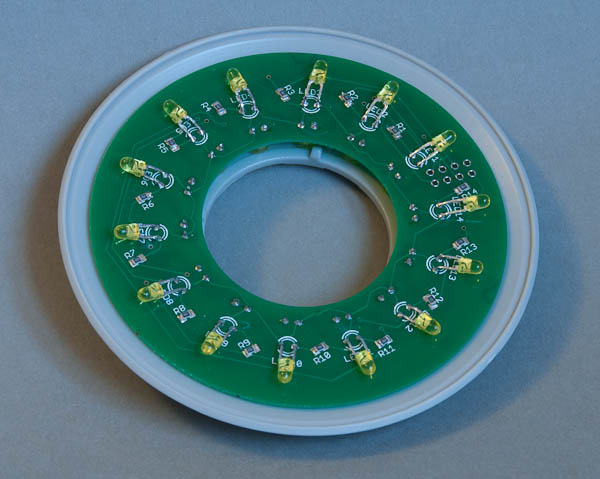
Looks so neat for something so small and fiddly – especially compared to the web of wires in the original 🙂
do you have these still for sale pleaseif yes then how much thanks.